Multi-Part Features Finder
Multi-Part Features Finder locates multiple parts of the same type on a tray. It receives one image of multiple parts on a tray from a camera, locates these parts by searching them in all user-defined sub-regions, and outputs all found parts' feature lists. The output feature lists will be used for Multi-part alignment computation to guide a gripper to pick these parts in correct poses (Align to Pick), or to guide a stage to align these parts to their golden poses one by one for mechanical operating such as gluing (Align to Base).
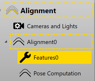
Multi-Part Features Finder is generated if the feature type was selected as "Multiple Part" in the corresponding finder in the Configuration Wizard. The finder's configuration HMI is under Alignment category in the setup mode of the application .
It takes two steps to configure a multiple-part finder: 1) Sub region configuration, 2) Vision tool setting. Sub region configuration is to configure search region for each pocket of the tray (functions available on MulRegionSetting sub-page). Vision tool setting is to set vision tools to locate parts in all sub regions (functions available on ToolBlockSetting sub-page).
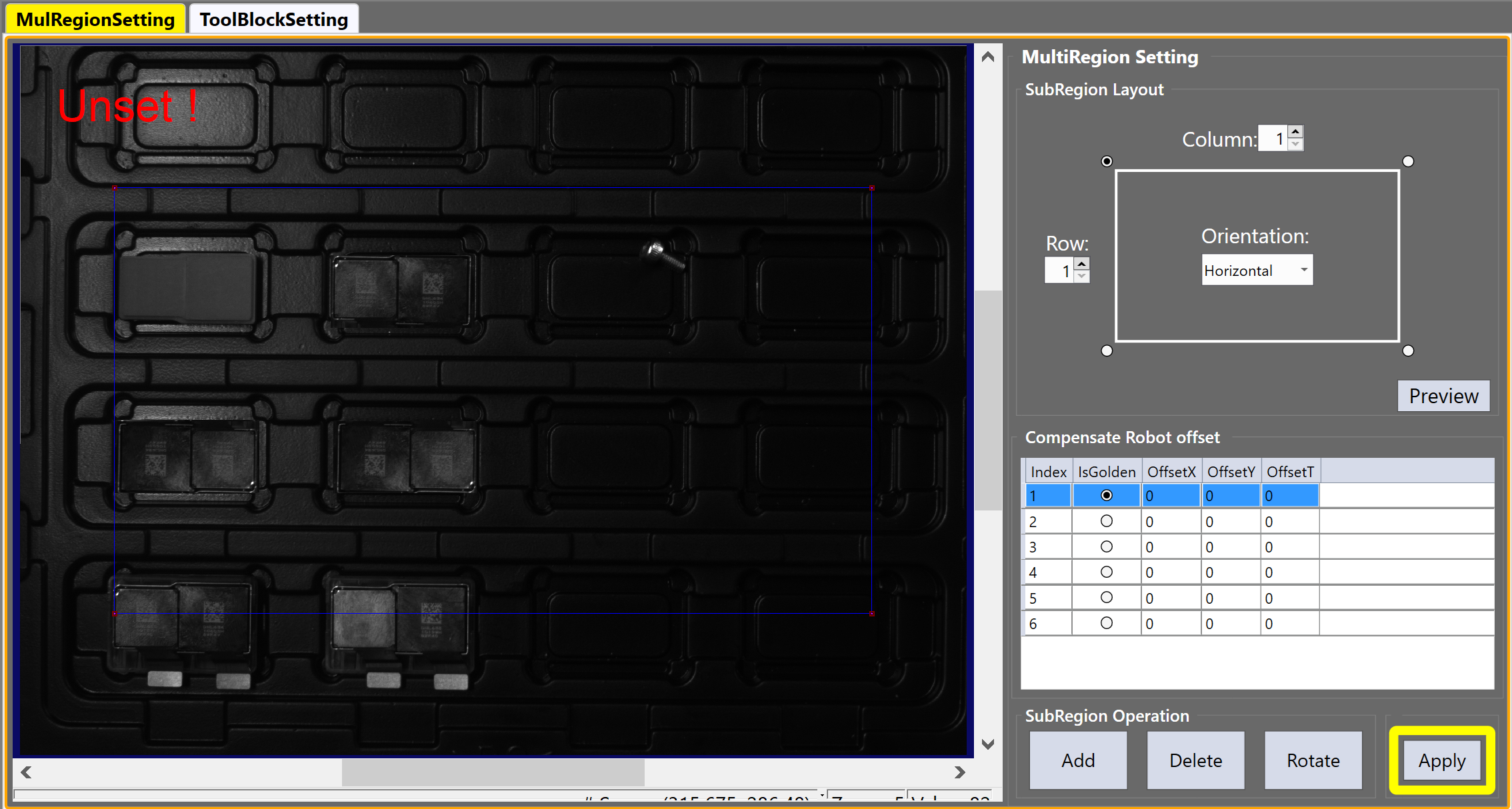
MulRegionSetting
MulRegionSetting page allows users to generate default sub regions out of a grid, edit the generated sub regions, configure parts' directions in all sub regions, and add offsets for each sub region so that the gripper can pick every part accurately.
Here are steps to set up sub regions:
Generates Sub Regions
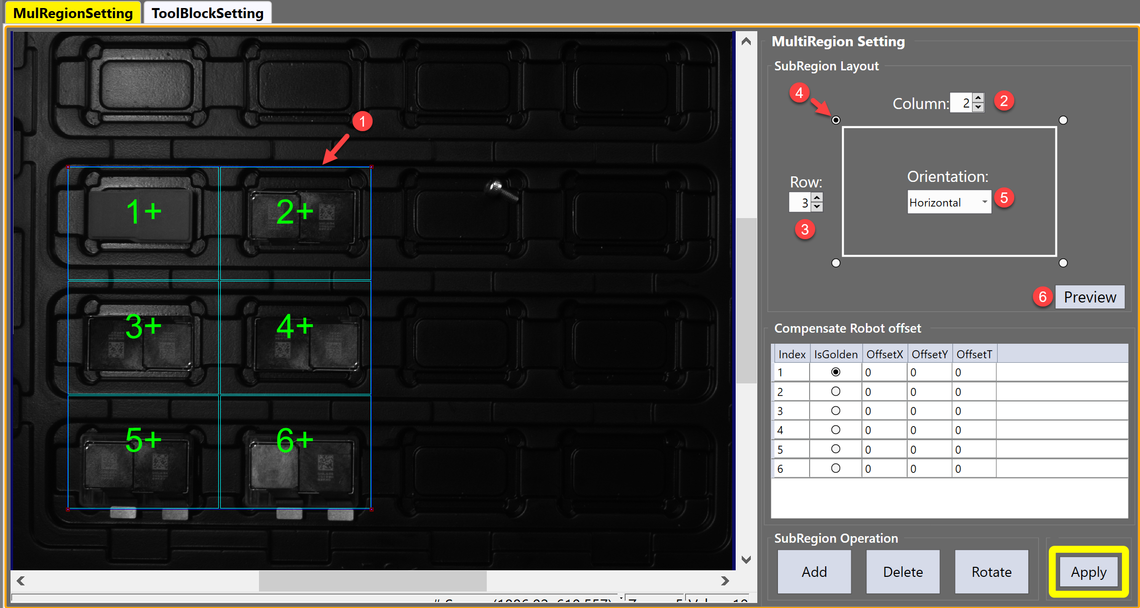
One can generate multiple sub regions by dividing a overall search region by several rows and columns.
-
Adjust the location and size of the blue rectangle on the image to confirm the overall search region (Step 1)
-
Input column and row numbers of the grid (Step 2 and 3)
-
Select the starting corner and indexing direction for sub regions (Step 4 and 5)
-
Click "Preview" button to check the sub region division result (Step 6)
Configure Sub Regions
This step allows users to fine tune sub regions sizes and locations, set parts directions, and configure which part should be used for golden pose training.
-
Manually adjust sub regions' sizes and locations if needed
-
Choose one part as master part to train golden pose
-
Check if all other parts' directions are the same with master part's. If they are the opposite, click "Rotate" button to rotate them 180 degrees.
After rotating, the color of the index label will be changed from green to purple, the "+" sign within the label will also be changed to "-". The configuration of parts directions helps vision tool to minimize the search angle range for all parts during run time feature finding so as to save processing time.
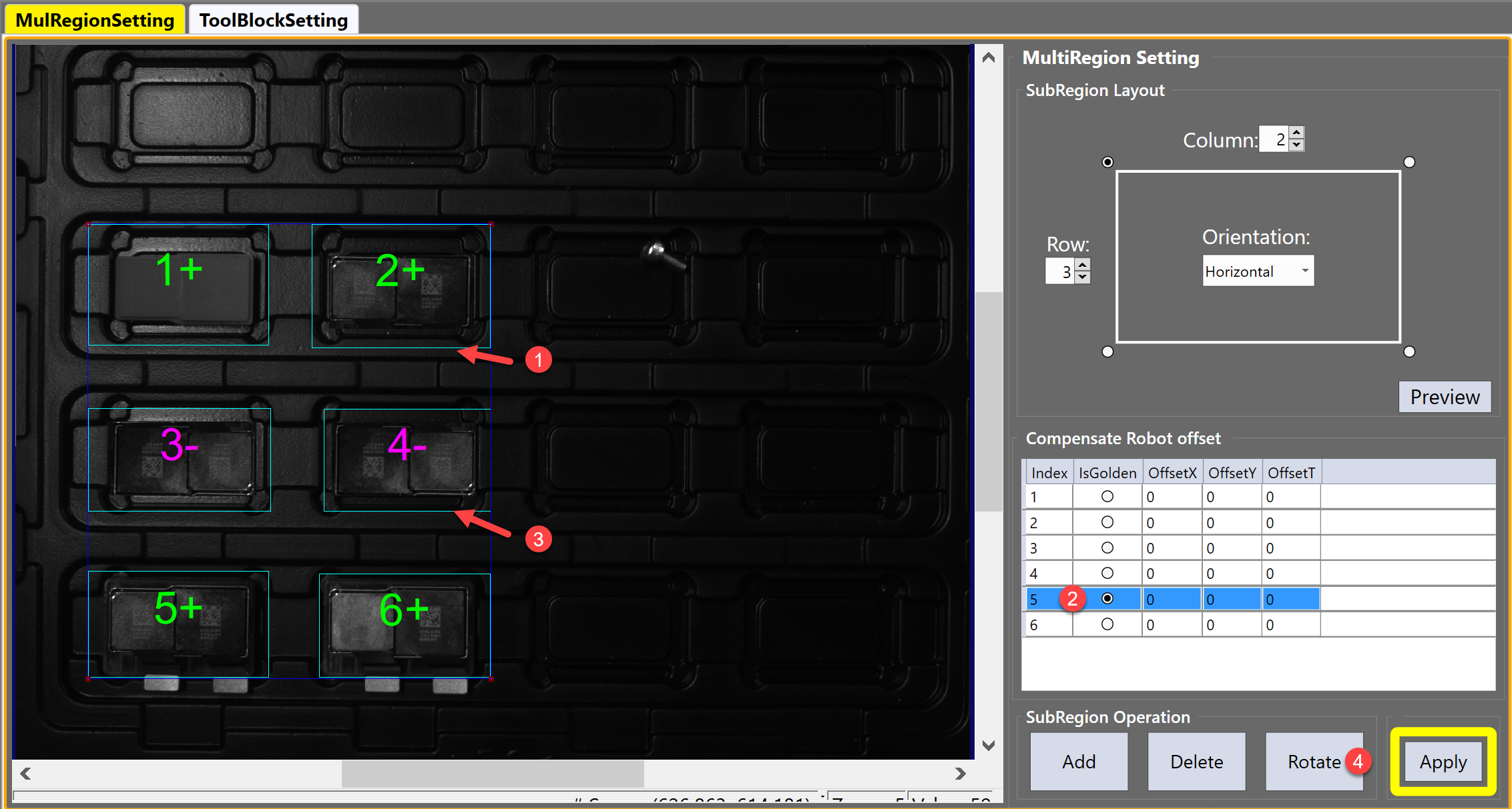
Add or Delete Sub Regions
-
If there is any extra sub region needs to be added, click the "Add" button to add and then edit it
-
If a sub region needs to be removed, select it first and then click the "Delete" button .
Offsets Sub Regions
Gripper's translation or rotation performance could be slightly different over different sub regions, these differences may lead to non-negligible errors during parts pickup. To make sure the gripper pick each part at a fixed relative pose one established during a training step, users can input offsets to each sub region to compensate these differences. These offsets can be manually calculated by engineers using results of several alignment tests.
Apply
After all sub regions' configurations are done, click "Apply" button to confirm.
ToolBlockSetting
ToolBlockSetting allows users to customize vision tools for all sub regions. Since all parts are of the same type, the user only needs to configure vision tools in one sub region during the setup, then the finder will automatically search parts in all sub regions during run time.
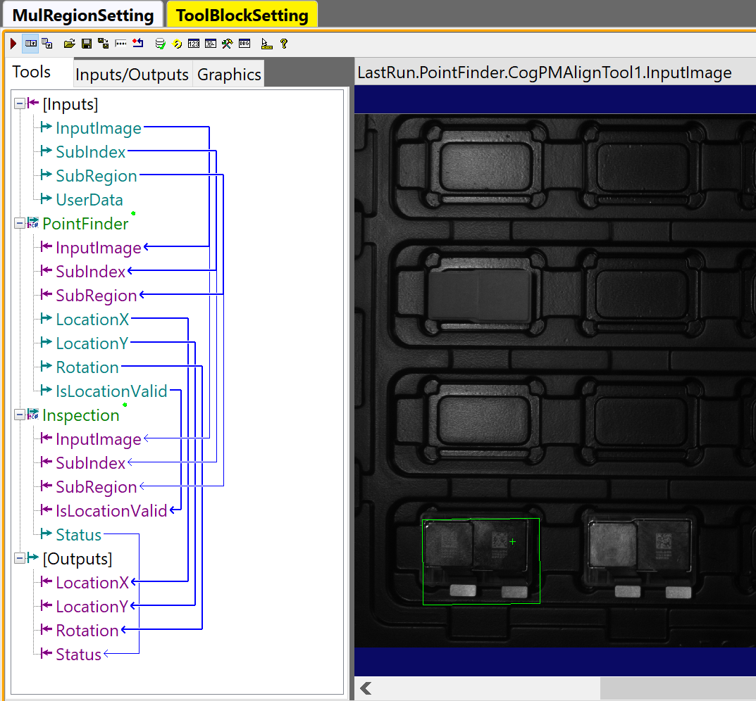
ToolBlockSetting page already has a default custom toolblock loaded to minimize users' work. This toolblock locates and inspects the part within an input sub region. The inputs and outputs of the toolblock are as below:
Inputs
| Name | Type | Description |
|---|---|---|
| InputImage | Cognex.VisionPro.ICogImage | Input image of the current feature finder |
| SubIndex | Integer | The index of current sub region |
| SubRegion | Cognex.VisionPro.CogRectangleAffine | Current sub region |
| UserData | Cognex.VisionPro.CogDictionary | Input UserData of the current feature finder |
Outputs
| Name | Type | Description |
|---|---|---|
| LocationX | Double | X element of the pose of the found part within current sub region; if the part is not found, this value will be 999999. |
| LocationY | Double | Y element of the pose of the found part within current sub region; if the part is not found, this value will be 999999. |
| Rotation | Double | Theta element of the pose of the found part within current sub region; if the part is not found, this value will be 999999. |
| Status | Integer |
Whether the part is found within the current sub region 1: found 0: not found |
Tools
The default toolblock has two parts: Point Finder and Inspection.
Point Finder
Point Finder is used to locate part within a sub region. By default it uses a CogPMAlignTool to find a part. However, users can replace it with other tools according to the requirements of the application.
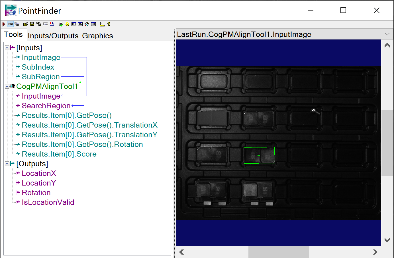
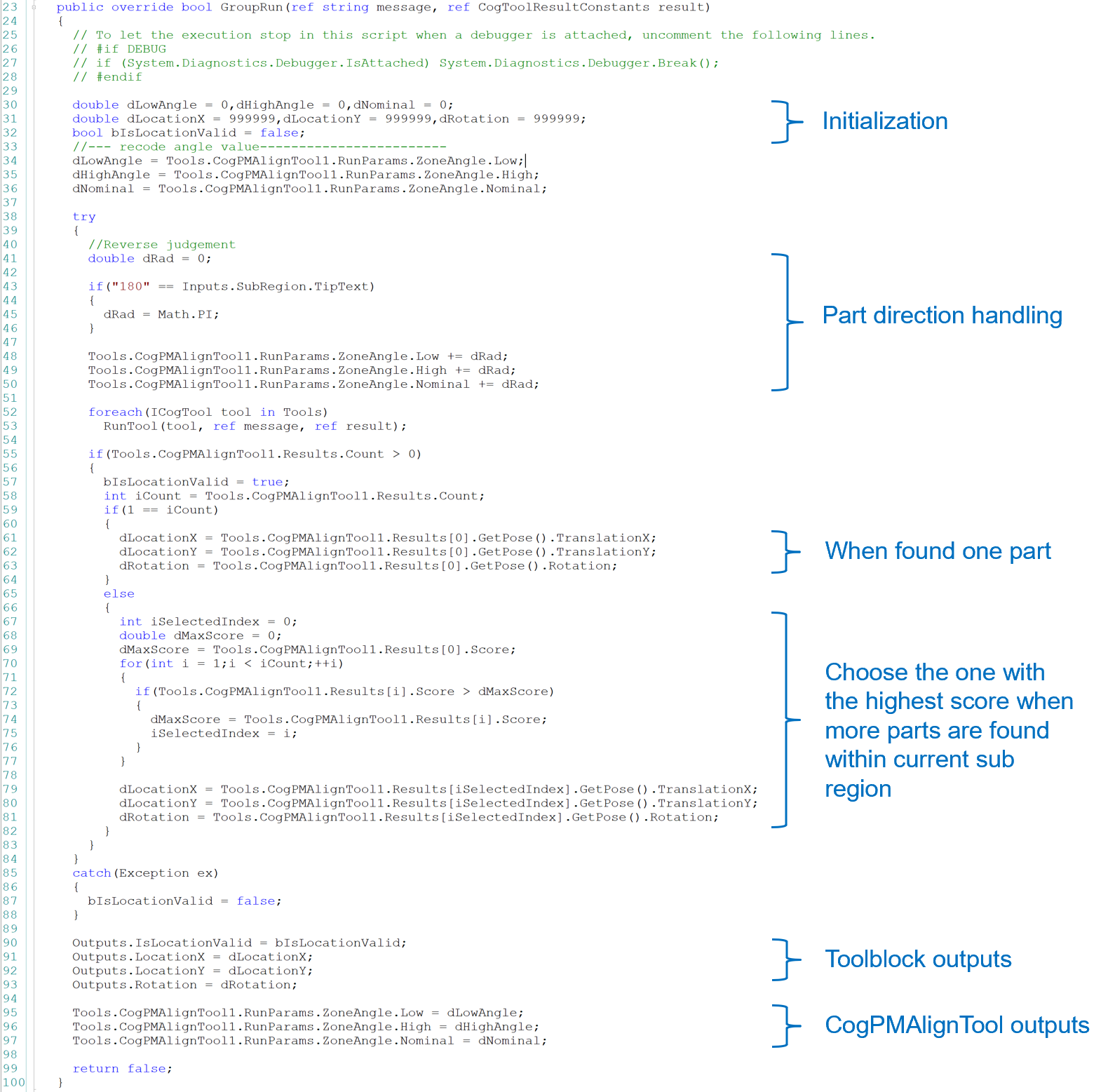
The values of output pins of Point Finder toolblock was given by scripting as below. Users do not need to modify it if CogPMAlignTool is used for part locating.
Inspections
Inspections allows users to customize inspection for each sub region, such as presence check, code reading, etc.
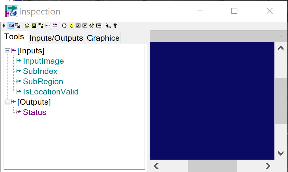
Its inputs are as below:
| Name | Type | Description |
|---|---|---|
| InputImage | Cognex.VisionPro.ICogImage | Input image of the current feature finder |
| SubIndex | Integer | The index of current sub region |
| SubRegion | Cognex.VisionPro.CogRectangleAffine | Current sub region |
| IsLocationValid | Boolean | Indicates whether the part was found in the previous PointFinder toolblock |
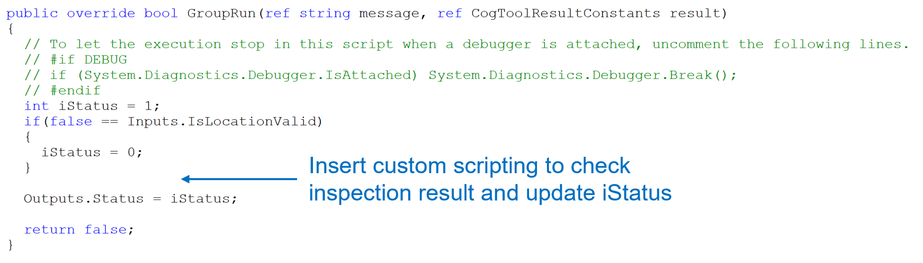
The output of Inspection toolblock is an Boolean object which only indicates whether the Point Finder and Inspection results are both successful for the current sub region. However, it now only indicates the Point Finder result as the Inspection toolblock is empty inside by default. The script below shows where the value of iStatus output should be updated after specific tools were added by user in the Inspection toolblock.
Golden Pose Training
After the multi-part features finder is configured, click the corresponding "TA" command button on the Manual Button Control in manual mode to train the golden pose. Only the master part is trained as the golden pose, other parts will share the same golden pose during alignment pose computation. If it is "Align To Gripper" type of alignment, "TT" command should also be sent to the vision system to register motion device's pose during train time.
Recipe Saving
After the multi-part features finder has been configured and golden pose has been trained, save the corresponding Alignment recipe.
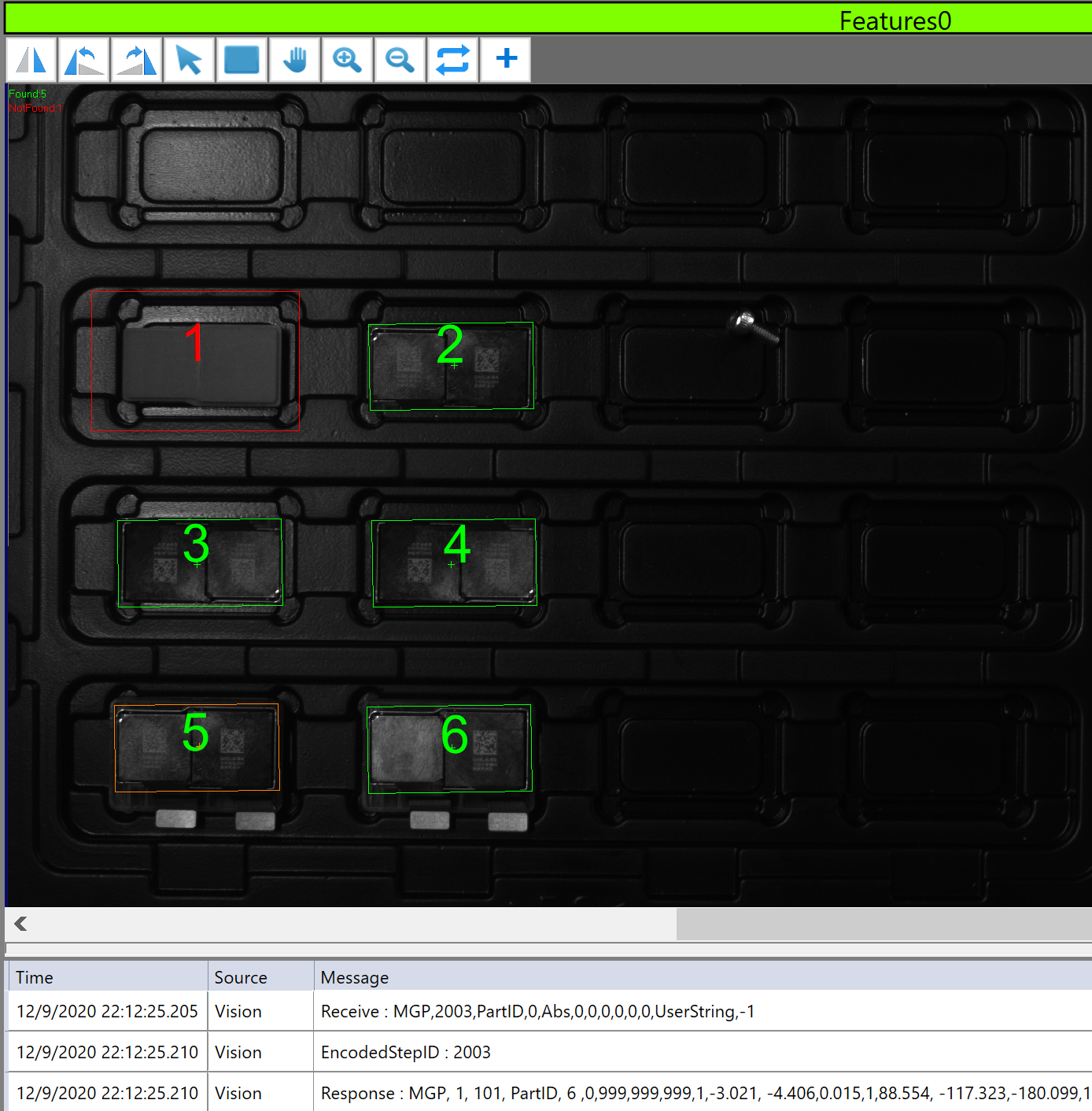
Run
During run time, the multi-part features finder searches parts in all sub regions and returns each sub region's found status, part's locations if they are found. On the image display, if a part is found within a sub region, it will be labeled in green ( the master part's region will be marked as orange), otherwise in red.